Bài hướng dẫn cách sử dụng module MEMS MPU6050 với Raspberry Pi Pico để đo các giá trị gia tốc, hướng (Gyroscope) và nhiệt độ bằng firmware MicroPython. Đầu tiên là phần giới thiệu về MPU6050 như sơ đồ sơ đồ chân, cấu hình chân. Thứ hai, chúng ta sẽ xem cách tải thư viện hỗ trợ lập trình MPU6050 MicroPython lên Raspberry Pi Pico bằng phần mềm Thonny IDE. Cuối cùng, là cách lấy giá trị gia tốc, con quay hồi chuyển (Gyroscope) và nhiệt độ từ module MPU6050 với Raspberry Pi Pico.
Yêu cầu bắt buộc:
Trước khi bắt đầu bài học này, hãy đảm bảo rằng bạn đã quen thuộc và đã cài đặt phiên bản Python3 mới nhất trong PC cũng như thiết lập MicroPython trên Raspberry Pi Pico. Ngoài ra, bạn nên phần mềm lập trình (IDE) để thực hiện lập trình. Chúng ta sẽ sử dụng Thonny IDE.
Giới thiệu module cảm biến MPU6050
Module cảm biến MPU6050 là module MEMS (Micro-Electro-Mechanical System) có IC MPU6050 tích hợp. Con chip này chứa một con quay hồi chuyển ba trục, gia tốc kế ba trục và bộ xử lý điều khiển chuyển động tín hiệu digital được tích hợp trong một package IC duy nhất. Trên hết, nó cũng có một cảm biến nhiệt độ tích hợp. Tất cả các cảm biến này được sản xuất trên cùng một khuôn của MPU6050. Có thể sử dụng module này để đo vận tốc, gia tốc, hướng, độ dịch chuyển và các thông số liên quan đến chuyển động khác. Ngày nay, tất cả các điện thoại thông minh hiện đại đều được tích hợp cảm biến chuyển động quán tính. MPU6050 cũng thuộc một trong những loại cảm biến này. Cảm biến này cho phép thực hiện một giải pháp hoàn chỉnh cho bất kỳ hệ thống theo dõi chuyển động sáu trục.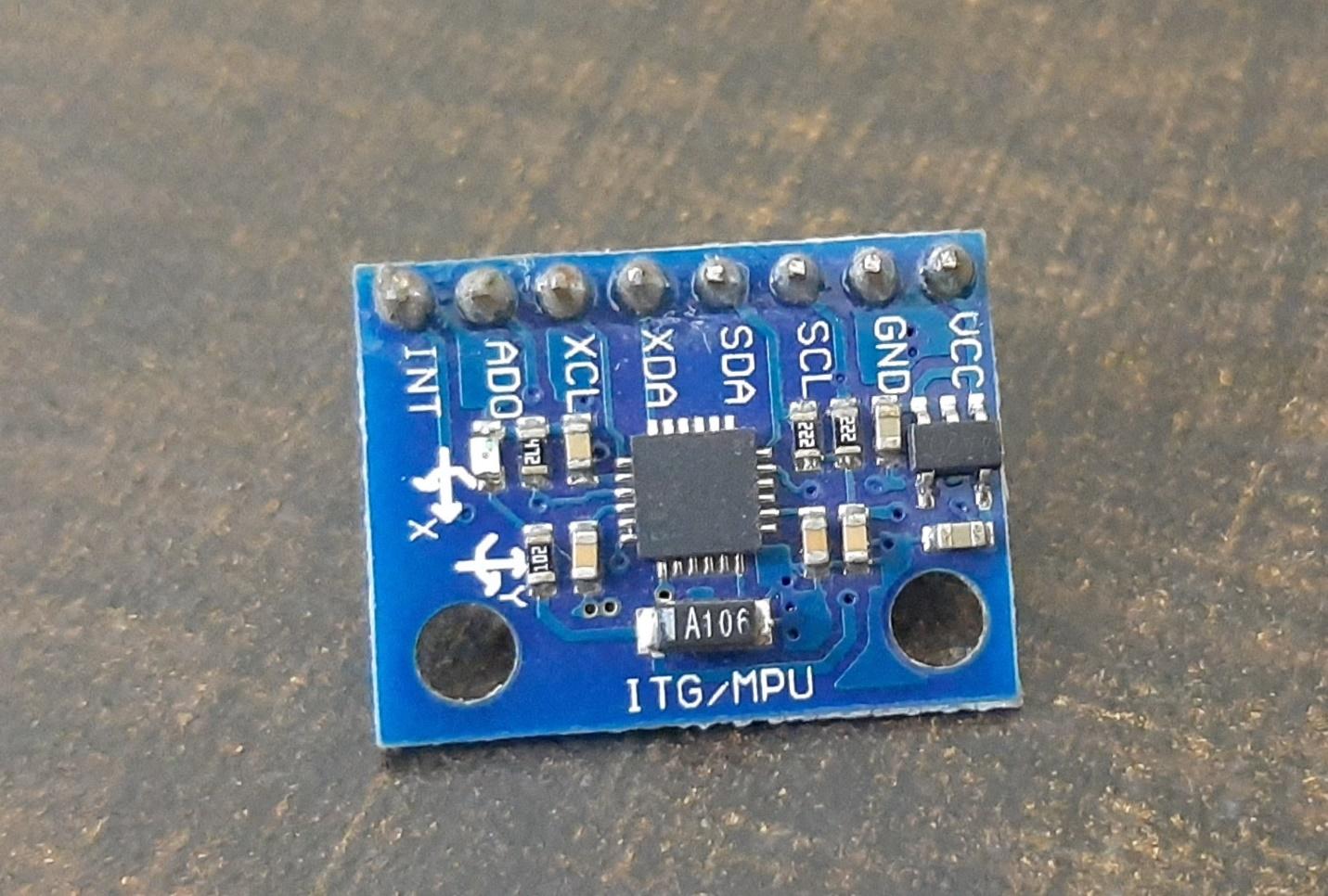
Một trong những tính năng quan trọng nhất của cảm biến MPU6050 MEMS là có chứa bộ xử lý chuyển động kỹ thuật số (DMP) mạnh mẽ và có khả năng xử lý cao. DMP thực hiện tất cả các phép tính phức tạp bên trong trước khi cho phép người dùng đọc dữ liệu từ cảm biến trên cổng I2C. Điều đó có nghĩa là không phải thực hiện các phép tính công suất cao trên vi điều khiển sau khi đọc dữ liệu từ chip MPU6050.
Đầu ra dữ liệu theo giao thức I2C
Như đã thảo luận trước đó, MPU6050 cho dữ liệu đầu ra trên một bus I2C. Do đó, có thể sử dụng giao diện bus I2C của MPU6050 để truyền giá trị gia tốc kế 3 trục và con quay hồi chuyển 3 trục sang cho Raspberry Pi Pico. Nói cách khác, có thể sử dụng bất kỳ bộ vi điều khiển nào có cổng giao thức I2C để đọc dữ liệu đầu ra của cảm biến. Có một địa chỉ chuyên dụng thể gán cho từng giá trị tham số ở giao diện I2C MPU6050. Có thể sử dụng các địa chỉ này để nhận các giá trị chính xác từ một cảm biến như gia tốc, con quay hồi chuyển (Gyroscope) và nhiệt độ.
Một trong những ưu điểm của việc sử dụng giao tiếp I2C của cảm biến này là có thể giao tiếp nhiều module MPU5060 với một bộ vi điều khiển duy nhất.
Chân cắm của MPU6050
Chip MPU6050 có 24 chân. Nhưng chỉ có 8 chân được tiếp xúc trên sơ đồ chân của module. Module cảm biến MEMS bao gồm 8 chân và các chân này được sử dụng cho các cấu hình khác nhau và được sử dụng để đọc dữ liệu từ cảm biến.
Dưới đây sơ đồ chân của module MEMS MPU6050:
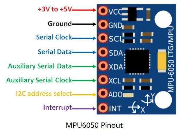
Mô tả các chân
Đầu tiên là chân VCC được sử dụng để cấp nguồn cho cảm biến và điện áp DC từ 3 đến 5 volt. Nhưng thông thường, nguồn điện 5V được cấp trực tiếp từ vi điều khiển.
Chân thứ hai là chân GND được kết nối với chân GND của vi điều khiển.
Chân số ba là chân SCL (xung clock) được kết nối với chân SCL của vi điều khiển. SCL là một chân xung clock được sử dụng trong giao tiếp I2C. Xung clock được cấp bởi thiết bị chính là vi điều khiển.
Chân thứ tư là chân SDA (Chân dữ liệu truyền nối tiếp) được sử dụng để truyền dữ liệu đến vi điều khiển. Kết nối chân SDA của MPU6050 với chân SDA của vi điều khiển
Chân thứ năm là chân XDA (Chân dữ liệu truyền nối tiếp phụ) được sử dụng để kết nối các module I2C bên ngoài với MPU6050, chẳng hạn như module từ kế. Nhưng việc sử dụng chân này là tùy chọn.
Chân thứ sáu là chân XCL (Chân nhận xung clock phụ) cũng được kết nối với một cảm biến có giao thức 12C khác để kích hoạt nó từ module cảm biến này.
AD0 (Chân7): AD0 (Chân chọn địa chỉ) là chân chọn địa chỉ slave12C. Ví dụ: nếu sử dụng nhiều module MPU6050 với một bộ vi điều khiển, thì chân này được sử dụng để thay đổi địa chỉ slave cho từng cảm biến MEMS. Bằng cách đó, mỗi cảm biến MEMS có thể được phân biệt dễ dàng trên một bus I2C với địa chỉ duy nhất.
INT (Chân 8): Chân INT (chân ngắt) là chân đầu ra digital của bộ ngắt và được sử dụng để báo cho bộ vi điều khiển rằng dữ liệu sẵn sàng để đọc từ module cảm biến MPU6050.
Giao tiếp MPU6050 với Raspberry Pi Pico
Như bạn thấy, MPU6050 có 8 đầu ra nhưng để kết nối với Raspberry Pi Pico, sẽ chỉ yêu cầu bốn chân đầu tiên. Đó là VCC, GND, SCL và SDA.
Chân I2C củaRaspberry Pi Pico
Raspberry Pi Pico có hai bộ điều khiển giao thức I2C. Cả hai bộ điều khiển I2C đều có thể truy cập thông qua các chân GPIO của Raspberry Pi Pico. Bảng sau đây là kết nối của các chân GPIO với cả hai bộ điều khiển I2C. Mỗi kết nối của bộ điều khiển có thể được cấu hình thông qua nhiều chân GPIO như trong hình. Nhưng trước khi sử dụng bộ điều khiển I2C, nên cấu hình trong phần mềm các chân GPIO mà bạn muốn sử dụng làm bộ điều khiển I2C cụ thể.
|
Bộ điều khiển giao thức I2C
|
Các chân GPIO
|
|
I2C0 – SDA
|
GP0/GP4/GP8/GP12/GP16/GP20
|
|
I2C0 – SCL
|
GP1/GP5/GP9/GP13/GP17/GP21
|
|
I2C1 – SDA
|
GP2/GP6/GP10/GP14/GP18/GP26
|
|
I2C1 – SCL
|
GP3/GP7/GP11/GP15/GP19/GP27
|
Các kết nối chân giữa hai thiết bị đang sử dụng được mô tả như bên dưới.
|
MPU6050
|
Raspberry Pi Pico
|
|
VCC
|
3.3V
|
|
SDA
|
GP0 (I2C0 SDA)
|
|
SCL
|
GP1 (I2C0 SCL)
|
|
GND
|
GND
|
Chân VCC được kết nối với chân 3,3V từ Raspberry Pi Pico để cấp nguồn. Cả hai chân GND của hai thiết bị được kết nối chung. Chân SCL của MPU6050 được kết nối với chân I2C0 SCL của Pi Pico. Tương tự, chân SDA được kết nối với chân I2C0 SDA của Pi Pico.
Chúng tôi đã sử dụng các kết nối giống như được chỉ định trong bảng trên. Tuy nhiên, bạn cũng có thể sử dụng với các kết hợp chân SDA/SCL khác. 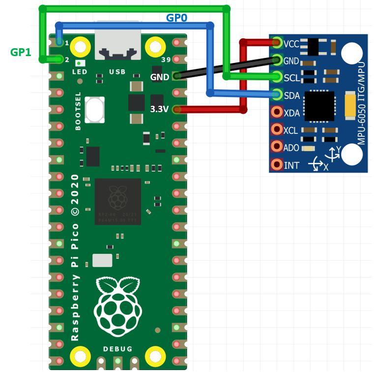
Sơ đồ kết nối Raspberry Pi Pico và MPU6050
Thư viện hỗ trợ lập trình MPU6050 MicroPython
Đối với dự án này, sẽ yêu cầu hai thư viện: imu.py và vector3d.py. Sao chép cả hai thư viện này và lưu vào Raspberry Pi Pico với tên tệp tương ứng. Mở một tệp mới trong Thonny. Sao chép các thư viện dưới đây. Lưu vào Raspberry Pi Pico với tên imu.py và vector32.py trong thư mục lib.
imu.py
# imu.py MicroPython driver for the InvenSense inertial measurement units
# This is the base class
# Adapted from Sebastian Plamauer's MPU9150 driver:
# https://github.com/micropython-IMU/micropython-mpu9150.git
# Authors Peter Hinch, Sebastian Plamauer
# V0.2 17th May 2017 Platform independent: utime and machine replace pyb
'''
mpu9250 is a micropython module for the InvenSense MPU9250 sensor.
It measures acceleration, turn rate and the magnetic field in three axis.
mpu9150 driver modified for the MPU9250 by Peter Hinch
The MIT License (MIT)
Copyright (c) 2014 Sebastian Plamauer, oeplse@gmail.com, Peter Hinch
Permission is hereby granted, free of charge, to any person obtaining a copy
of this software and associated documentation files (the "Software"), to deal
in the Software without restriction, including without limitation the rights
to use, copy, modify, merge, publish, distribute, sublicense, and/or sell
copies of the Software, and to permit persons to whom the Software is
furnished to do so, subject to the following conditions:
The above copyright notice and this permission notice shall be included in
all copies or substantial portions of the Software.
THE SOFTWARE IS PROVIDED "AS IS", WITHOUT WARRANTY OF ANY KIND, EXPRESS OR
IMPLIED, INCLUDING BUT NOT LIMITED TO THE WARRANTIES OF MERCHANTABILITY,
FITNESS FOR A PARTICULAR PURPOSE AND NONINFRINGEMENT. IN NO EVENT SHALL THE
AUTHORS OR COPYRIGHT HOLDERS BE LIABLE FOR ANY CLAIM, DAMAGES OR OTHER
LIABILITY, WHETHER IN AN ACTION OF CONTRACT, TORT OR OTHERWISE, ARISING FROM,
OUT OF OR IN CONNECTION WITH THE SOFTWARE OR THE USE OR OTHER DEALINGS IN
THE SOFTWARE.
'''
# User access is now by properties e.g.
# myimu = MPU9250('X')
# magx = myimu.mag.x
# accelxyz = myimu.accel.xyz
# Error handling: on code used for initialisation, abort with message
# At runtime try to continue returning last good data value. We don't want aircraft
# crashing. However if the I2C has crashed we're probably stuffed.
from utime import sleep_ms
from machine import I2C
from vector3d import Vector3d
class MPUException(OSError):
'''
Exception for MPU devices
'''
pass
def bytes_toint(msb, lsb):
'''
Convert two bytes to signed integer (big endian)
for little endian reverse msb, lsb arguments
Can be used in an interrupt handler
'''
if not msb & 0x80:
return msb << 8 | lsb # +ve
return - (((msb ^ 255) << 8) | (lsb ^ 255) + 1)
class MPU6050(object):
'''
Module for InvenSense IMUs. Base class implements MPU6050 6DOF sensor, with
features common to MPU9150 and MPU9250 9DOF sensors.
'''
_I2Cerror = "I2C failure when communicating with IMU"
_mpu_addr = (104, 105) # addresses of MPU9150/MPU6050. There can be two devices
_chip_id = 104
def __init__(self, side_str, device_addr=None, transposition=(0, 1, 2), scaling=(1, 1, 1)):
self._accel = Vector3d(transposition, scaling, self._accel_callback)
self._gyro = Vector3d(transposition, scaling, self._gyro_callback)
self.buf1 = bytearray(1) # Pre-allocated buffers for reads: allows reads to
self.buf2 = bytearray(2) # be done in interrupt handlers
self.buf3 = bytearray(3)
self.buf6 = bytearray(6)
sleep_ms(200) # Ensure PSU and device have settled
if isinstance(side_str, str): # Non-pyb targets may use other than X or Y
self._mpu_i2c = I2C(side_str)
elif hasattr(side_str, 'readfrom'): # Soft or hard I2C instance. See issue #3097
self._mpu_i2c = side_str
else:
raise ValueError("Invalid I2C instance")
if device_addr is None:
devices = set(self._mpu_i2c.scan())
mpus = devices.intersection(set(self._mpu_addr))
number_of_mpus = len(mpus)
if number_of_mpus == 0:
raise MPUException("No MPU's detected")
elif number_of_mpus == 1:
self.mpu_addr = mpus.pop()
else:
raise ValueError("Two MPU's detected: must specify a device address")
else:
if device_addr not in (0, 1):
raise ValueError('Device address must be 0 or 1')
self.mpu_addr = self._mpu_addr[device_addr]
self.chip_id # Test communication by reading chip_id: throws exception on error
# Can communicate with chip. Set it up.
self.wake() # wake it up
self.passthrough = True # Enable mag access from main I2C bus
self.accel_range = 0 # default to highest sensitivity
self.gyro_range = 0 # Likewise for gyro
# read from device
def _read(self, buf, memaddr, addr): # addr = I2C device address, memaddr = memory location within the I2C device
'''
Read bytes to pre-allocated buffer Caller traps OSError.
'''
self._mpu_i2c.readfrom_mem_into(addr, memaddr, buf)
# write to device
def _write(self, data, memaddr, addr):
'''
Perform a memory write. Caller should trap OSError.
'''
self.buf1[0] = data
self._mpu_i2c.writeto_mem(addr, memaddr, self.buf1)
# wake
def wake(self):
'''
Wakes the device.
'''
try:
self._write(0x01, 0x6B, self.mpu_addr) # Use best clock source
except OSError:
raise MPUException(self._I2Cerror)
return 'awake'
# mode
def sleep(self):
'''
Sets the device to sleep mode.
'''
try:
self._write(0x40, 0x6B, self.mpu_addr)
except OSError:
raise MPUException(self._I2Cerror)
return 'asleep'
# chip_id
@property
def chip_id(self):
'''
Returns Chip ID
'''
try:
self._read(self.buf1, 0x75, self.mpu_addr)
except OSError:
raise MPUException(self._I2Cerror)
chip_id = int(self.buf1[0])
if chip_id != self._chip_id:
raise ValueError('Bad chip ID retrieved: MPU communication failure')
return chip_id
@property
def sensors(self):
'''
returns sensor objects accel, gyro
'''
return self._accel, self._gyro
# get temperature
@property
def temperature(self):
'''
Returns the temperature in degree C.
'''
try:
self._read(self.buf2, 0x41, self.mpu_addr)
except OSError:
raise MPUException(self._I2Cerror)
return bytes_toint(self.buf2[0], self.buf2[1])/340 + 35 # I think
# passthrough
@property
def passthrough(self):
'''
Returns passthrough mode True or False
'''
try:
self._read(self.buf1, 0x37, self.mpu_addr)
return self.buf1[0] & 0x02 > 0
except OSError:
raise MPUException(self._I2Cerror)
@passthrough.setter
def passthrough(self, mode):
'''
Sets passthrough mode True or False
'''
if type(mode) is bool:
val = 2 if mode else 0
try:
self._write(val, 0x37, self.mpu_addr) # I think this is right.
self._write(0x00, 0x6A, self.mpu_addr)
except OSError:
raise MPUException(self._I2Cerror)
else:
raise ValueError('pass either True or False')
# sample rate. Not sure why you'd ever want to reduce this from the default.
@property
def sample_rate(self):
'''
Get sample rate as per Register Map document section 4.4
SAMPLE_RATE= Internal_Sample_Rate / (1 + rate)
default rate is zero i.e. sample at internal rate.
'''
try:
self._read(self.buf1, 0x19, self.mpu_addr)
return self.buf1[0]
except OSError:
raise MPUException(self._I2Cerror)
@sample_rate.setter
def sample_rate(self, rate):
'''
Set sample rate as per Register Map document section 4.4
'''
if rate < 0 or rate > 255:
raise ValueError("Rate must be in range 0-255")
try:
self._write(rate, 0x19, self.mpu_addr)
except OSError:
raise MPUException(self._I2Cerror)
# Low pass filters. Using the filter_range property of the MPU9250 is
# harmless but gyro_filter_range is preferred and offers an extra setting.
@property
def filter_range(self):
'''
Returns the gyro and temperature sensor low pass filter cutoff frequency
Pass: 0 1 2 3 4 5 6
Cutoff (Hz): 250 184 92 41 20 10 5
Sample rate (KHz): 8 1 1 1 1 1 1
'''
try:
self._read(self.buf1, 0x1A, self.mpu_addr)
res = self.buf1[0] & 7
except OSError:
raise MPUException(self._I2Cerror)
return res
@filter_range.setter
def filter_range(self, filt):
'''
Sets the gyro and temperature sensor low pass filter cutoff frequency
Pass: 0 1 2 3 4 5 6
Cutoff (Hz): 250 184 92 41 20 10 5
Sample rate (KHz): 8 1 1 1 1 1 1
'''
# set range
if filt in range(7):
try:
self._write(filt, 0x1A, self.mpu_addr)
except OSError:
raise MPUException(self._I2Cerror)
else:
raise ValueError('Filter coefficient must be between 0 and 6')
# accelerometer range
@property
def accel_range(self):
'''
Accelerometer range
Value: 0 1 2 3
for range +/-: 2 4 8 16 g
'''
try:
self._read(self.buf1, 0x1C, self.mpu_addr)
ari = self.buf1[0]//8
except OSError:
raise MPUException(self._I2Cerror)
return ari
@accel_range.setter
def accel_range(self, accel_range):
'''
Set accelerometer range
Pass: 0 1 2 3
for range +/-: 2 4 8 16 g
'''
ar_bytes = (0x00, 0x08, 0x10, 0x18)
if accel_range in range(len(ar_bytes)):
try:
self._write(ar_bytes[accel_range], 0x1C, self.mpu_addr)
except OSError:
raise MPUException(self._I2Cerror)
else:
raise ValueError('accel_range can only be 0, 1, 2 or 3')
# gyroscope range
@property
def gyro_range(self):
'''
Gyroscope range
Value: 0 1 2 3
for range +/-: 250 500 1000 2000 degrees/second
'''
# set range
try:
self._read(self.buf1, 0x1B, self.mpu_addr)
gri = self.buf1[0]//8
except OSError:
raise MPUException(self._I2Cerror)
return gri
@gyro_range.setter
def gyro_range(self, gyro_range):
'''
Set gyroscope range
Pass: 0 1 2 3
for range +/-: 250 500 1000 2000 degrees/second
'''
gr_bytes = (0x00, 0x08, 0x10, 0x18)
if gyro_range in range(len(gr_bytes)):
try:
self._write(gr_bytes[gyro_range], 0x1B, self.mpu_addr) # Sets fchoice = b11 which enables filter
except OSError:
raise MPUException(self._I2Cerror)
else:
raise ValueError('gyro_range can only be 0, 1, 2 or 3')
# Accelerometer
@property
def accel(self):
'''
Acceleremoter object
'''
return self._accel
def _accel_callback(self):
'''
Update accelerometer Vector3d object
'''
try:
self._read(self.buf6, 0x3B, self.mpu_addr)
except OSError:
raise MPUException(self._I2Cerror)
self._accel._ivector[0] = bytes_toint(self.buf6[0], self.buf6[1])
self._accel._ivector[1] = bytes_toint(self.buf6[2], self.buf6[3])
self._accel._ivector[2] = bytes_toint(self.buf6[4], self.buf6[5])
scale = (16384, 8192, 4096, 2048)
self._accel._vector[0] = self._accel._ivector[0]/scale[self.accel_range]
self._accel._vector[1] = self._accel._ivector[1]/scale[self.accel_range]
self._accel._vector[2] = self._accel._ivector[2]/scale[self.accel_range]
def get_accel_irq(self):
'''
For use in interrupt handlers. Sets self._accel._ivector[] to signed
unscaled integer accelerometer values
'''
self._read(self.buf6, 0x3B, self.mpu_addr)
self._accel._ivector[0] = bytes_toint(self.buf6[0], self.buf6[1])
self._accel._ivector[1] = bytes_toint(self.buf6[2], self.buf6[3])
self._accel._ivector[2] = bytes_toint(self.buf6[4], self.buf6[5])
# Gyro
@property
def gyro(self):
'''
Gyroscope object
'''
return self._gyro
def _gyro_callback(self):
'''
Update gyroscope Vector3d object
'''
try:
self._read(self.buf6, 0x43, self.mpu_addr)
except OSError:
raise MPUException(self._I2Cerror)
self._gyro._ivector[0] = bytes_toint(self.buf6[0], self.buf6[1])
self._gyro._ivector[1] = bytes_toint(self.buf6[2], self.buf6[3])
self._gyro._ivector[2] = bytes_toint(self.buf6[4], self.buf6[5])
scale = (131, 65.5, 32.8, 16.4)
self._gyro._vector[0] = self._gyro._ivector[0]/scale[self.gyro_range]
self._gyro._vector[1] = self._gyro._ivector[1]/scale[self.gyro_range]
self._gyro._vector[2] = self._gyro._ivector[2]/scale[self.gyro_range]
def get_gyro_irq(self):
'''
For use in interrupt handlers. Sets self._gyro._ivector[] to signed
unscaled integer gyro values. Error trapping disallowed.
'''
self._read(self.buf6, 0x43, self.mpu_addr)
self._gyro._ivector[0] = bytes_toint(self.buf6[0], self.buf6[1])
self._gyro._ivector[1] = bytes_toint(self.buf6[2], self.buf6[3])
self._gyro._ivector[2] = bytes_toint(self.buf6[4], self.buf6[5])
vector3d.py
# vector3d.py 3D vector class for use in inertial measurement unit drivers
# Authors Peter Hinch, Sebastian Plamauer
# V0.7 17th May 2017 pyb replaced with utime
# V0.6 18th June 2015
'''
The MIT License (MIT)
Copyright (c) 2014 Sebastian Plamauer, oeplse@gmail.com, Peter Hinch
Permission is hereby granted, free of charge, to any person obtaining a copy
of this software and associated documentation files (the "Software"), to deal
in the Software without restriction, including without limitation the rights
to use, copy, modify, merge, publish, distribute, sublicense, and/or sell
copies of the Software, and to permit persons to whom the Software is
furnished to do so, subject to the following conditions:
The above copyright notice and this permission notice shall be included in
all copies or substantial portions of the Software.
THE SOFTWARE IS PROVIDED "AS IS", WITHOUT WARRANTY OF ANY KIND, EXPRESS OR
IMPLIED, INCLUDING BUT NOT LIMITED TO THE WARRANTIES OF MERCHANTABILITY,
FITNESS FOR A PARTICULAR PURPOSE AND NONINFRINGEMENT. IN NO EVENT SHALL THE
AUTHORS OR COPYRIGHT HOLDERS BE LIABLE FOR ANY CLAIM, DAMAGES OR OTHER
LIABILITY, WHETHER IN AN ACTION OF CONTRACT, TORT OR OTHERWISE, ARISING FROM,
OUT OF OR IN CONNECTION WITH THE SOFTWARE OR THE USE OR OTHER DEALINGS IN
THE SOFTWARE.
'''
from utime import sleep_ms
from math import sqrt, degrees, acos, atan2
def default_wait():
'''
delay of 50 ms
'''
sleep_ms(50)
class Vector3d(object):
'''
Represents a vector in a 3D space using Cartesian coordinates.
Internally uses sensor relative coordinates.
Returns vehicle-relative x, y and z values.
'''
def __init__(self, transposition, scaling, update_function):
self._vector = [0, 0, 0]
self._ivector = [0, 0, 0]
self.cal = (0, 0, 0)
self.argcheck(transposition, "Transposition")
self.argcheck(scaling, "Scaling")
if set(transposition) != {0, 1, 2}:
raise ValueError('Transpose indices must be unique and in range 0-2')
self._scale = scaling
self._transpose = transposition
self.update = update_function
def argcheck(self, arg, name):
'''
checks if arguments are of correct length
'''
if len(arg) != 3 or not (type(arg) is list or type(arg) is tuple):
raise ValueError(name + ' must be a 3 element list or tuple')
def calibrate(self, stopfunc, waitfunc=default_wait):
'''
calibration routine, sets cal
'''
self.update()
maxvec = self._vector[:] # Initialise max and min lists with current values
minvec = self._vector[:]
while not stopfunc():
waitfunc()
self.update()
maxvec = list(map(max, maxvec, self._vector))
minvec = list(map(min, minvec, self._vector))
self.cal = tuple(map(lambda a, b: (a + b)/2, maxvec, minvec))
@property
def _calvector(self):
'''
Vector adjusted for calibration offsets
'''
return list(map(lambda val, offset: val - offset, self._vector, self.cal))
@property
def x(self): # Corrected, vehicle relative floating point values
self.update()
return self._calvector[self._transpose[0]] * self._scale[0]
@property
def y(self):
self.update()
return self._calvector[self._transpose[1]] * self._scale[1]
@property
def z(self):
self.update()
return self._calvector[self._transpose[2]] * self._scale[2]
@property
def xyz(self):
self.update()
return (self._calvector[self._transpose[0]] * self._scale[0],
self._calvector[self._transpose[1]] * self._scale[1],
self._calvector[self._transpose[2]] * self._scale[2])
@property
def magnitude(self):
x, y, z = self.xyz # All measurements must correspond to the same instant
return sqrt(x**2 + y**2 + z**2)
@property
def inclination(self):
x, y, z = self.xyz
return degrees(acos(z / sqrt(x**2 + y**2 + z**2)))
@property
def elevation(self):
return 90 - self.inclination
@property
def azimuth(self):
x, y, z = self.xyz
return degrees(atan2(y, x))
# Raw uncorrected integer values from sensor
@property
def ix(self):
return self._ivector[0]
@property
def iy(self):
return self._ivector[1]
@property
def iz(self):
return self._ivector[2]
@property
def ixyz(self):
return self._ivector
@property
def transpose(self):
return tuple(self._transpose)
@property
def scale(self):
return tuple(self._scale)
MicroPython MPU6050: Lấy giá trị gia tốc (Accelerometer), hướng (Gyroscope) và nhiệt độ
Sau khi tải hai thư viện được đề cập ở trên lên Raspberry Pi Pico, hãy lập trình bo mạch với MPU6050.
Bây giờ hãy xem một ví dụ để xem hoạt động của cảm biến. Chúng tôi sẽ kết nối cảm biến MPU6050 với Raspberry Pi Pico thông qua giao thức I2C như được hiển thị ở trên trong sơ đồ kết nối. Chúng tôi sẽ thấy code tập lệnh MicroPython và sau khi tải nó lên bảng mạch, sẽ thấy các thông số của gia tốc kế, Con quay hồi chuyển và nhiệt độ được xuất hiện trên màn hình shell console MicroPython.
Code MPU6050 MicroPython
Bây giờ, hãy xem code tập lệnh MicroPython cho MPU6050 để đọc cảm biến. Sao chép code sau vào tệp main.py và tải tệp main.py lên Raspberry Pi Pico.
Tập lệnh MicroPython này đọc các giá trị từ gia tốc kế, con quay hồi chuyển và nhiệt độ từ MPU-6050 qua các bus I2C và xuất chúng lên màn hình shell console MicroPython.
from imu import MPU6050
from time import sleep
from machine import Pin, I2C
i2c = I2C(0, sda=Pin(0), scl=Pin(1), freq=400000)
imu = MPU6050(i2c)
while True:
ax=round(imu.accel.x,2)
ay=round(imu.accel.y,2)
az=round(imu.accel.z,2)
gx=round(imu.gyro.x)
gy=round(imu.gyro.y)
gz=round(imu.gyro.z)
tem=round(imu.temperature,2)
print("ax",ax,"\t","ay",ay,"\t","az",az,"\t","gx",gx,"\t","gy",gy,"\t","gz",gz,"\t","Temperature",tem," ",end="\r")
sleep(0.2)
Giải thích code
Khai báo Libraries
Đầu tiên, sẽ import các chân và I2C từ module. Làm điều này để chỉ định chân cho giao tiếp I2C. Chúng tôi cũng import module sleep để làm thêm độ trễ giữa các lần đọc dữ liệu. Ngoài ra, import MPU6050 từ thư viện imu vừa tải lên trên bảng mạch.
from imu import MPU6050
from time import sleep
from machine import Pin, I2C
Khai báo các chân I2C của Raspberry Pi
Tiếp theo, sẽ khởi tạo các chân I2C GPIO tương ứng SCL và SDA. Chúng tôi đã sử dụng các chân I2C0 SCL và I2C0 SDA.
Tạo một phương thức I2C() có bốn tham số. Tham số đầu tiên là kênh I2C muốn sử dụng. Tham số thứ hai chỉ định chân I2C GPIO của bo mạch được kết nối trên bus SDA. Tham số thứ ba chỉ định chân I2C GPIO của bo mạch được kết nối với chân SCL. Tham số cuối cùng là kết nối tần số.
Chúng tôi đang đặt chân SCL ở chân 1 và SDA trên chân 0.
Tạo một biến object MPU6050 có tên là imu và truy cập các giá trị của cảm biến thông qua nó.
i2c = I2C(0, sda=Pin(0), scl=Pin(1), freq=400000)
imu = MPU6050(i2c)
Tiếp theo, chạy một vòng lặp vô hạn bên trong để truy cập các thông số đọc từ cảm biến. Sau đó xuất các giá trị lên màn hình shell console bằng cách sử dụng lệnh in. Thêm độ trễ sau khi mỗi lần dữ liệu được lưu vào bộ nhớ.
Các biến dữ liệu bao gồm gia tốc (x, y và z), con quay hồi chuyển (x, y và z) và nhiệt độ.
while True:
ax=round(imu.accel.x,2)
ay=round(imu.accel.y,2)
az=round(imu.accel.z,2)
gx=round(imu.gyro.x)
gy=round(imu.gyro.y)
gz=round(imu.gyro.z)
tem=round(imu.temperature,2)
print("ax",ax,"\t","ay",ay,"\t","az",az,"\t","gx",gx,"\t","gy",gy,"\t","gz",gz,"\t","Temperature",tem," ",end="\r")
sleep(0.2)
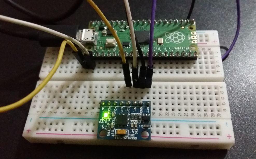
Demo
Để kiểm tra tập lệnh MicroPython cho MPU-6050 với Raspberry Pi Pico, hãy tải tệp main.py lên bảng mạch của bạn.
Bạn sẽ thấy các giá trị Gia tốc kế, Con quay hồi chuyển và Nhiệt độ trên màn hình shell console thay đổi liên tục khi di chuyển cảm biến theo các hướng khác nhau.

>>> 100+ Mã Sản Phẩm Dây Rút: https://mecsu.vn/san-pham/day-rut-nhua.5op
>>> 1000+ Mã Sản Phẩm Đầu Cosse: https://mecsu.vn/san-pham/dau-cosse.Q1j
Tán Lục Giác (469)
Tán Hàn - Weldnut (33)
Tán Keo - Lock Nut (226)
Tán Khía - Flange Nut (50)
Tán Dài (3)
Tán Bầu (39)
Tán Khóa (58)
Tán Cánh Chuồn (17)
Tán Cài (6)
Tán Vuông (11)
Vú Mỡ (Nipple Grease) (22)
Nut-With Knurled Heads (24)
Quick-Lock Nuts (16)
Blocks for Adjusting Bolts (207)
Threaded Stopper Blocks (52)
Bearing Lock Nuts (78)
Lông Đền Phẳng - Flat Washer (312)
Lông Đền Vênh - Spring Washer (238)
Lông Đền Vuông (25)
Lông Đền Răng (91)
Lông Đền Vênh Loại Lượn Sóng (7)
Lông Đền Lượn Sóng (15)
Lông Đền Lò Xo Đĩa (25)
Lông Đền Nord-Lock (95)
Lông Đền Heico-Lock (101)
Lông Đền Răng Cưa (77)
Lông Đền Dầu (Bonded Seal) (29)
Lông Đền Chén (1)
Lông Đền Cầu (5)
Lông Đền Làm Kín (Dạng Phớt) (3)
Gối Đỡ Vòng Bi UCP (69)
Gối Đỡ Vòng Bi UCF (46)
Gối Đỡ Vòng Bi UCPA (6)
Gối Đỡ Vòng Bi UCFC (16)
Gối Đỡ Vòng Bi UCFL (26)
Gối Đỡ Vòng Bi UCFK (3)
Gối Đỡ Vòng Bi UCT (16)
Gối Đỡ UCHA (2)
Gối Đỡ Vòng Bi Đũa Hình Tròn (1)
 Vòng Bi Chuyên Dùng Cho Gối Đỡ (1)
Vòng Bi UC (45)
Vòng Bi UK (3)
Vỏ Gối Đỡ (22)
Phụ Kiện Gối Đỡ (22)
Con Lăn Bi Loại Ép Chặt (7)
Con Lăn Bi Loại Thân Lục Giác (14)
Con Lăn Bi Loại Thân Tròn (5)
Con Lăn Bi Loại Đế Mặt Bích (4)
Con Lăn Bi Loại Đinh Tán Đầu Tròn (4)
Con Lăn Bi Loại Vít Cấy (12)
Con Lăn Bi Loại Đẩy Bi Có Ren (3)
Con Lăn Bi Loại Đẩy Bi Không Ren (3)
Ball Rollers Press (1)
Ball Plungers Roller (10)
Press Fit Plungers Roller (6)
Đầu Nối Nhanh Khí Nén Thẳng (1340)
Đầu Nối Nhanh Khí Nén Thẳng - Có Ren (2935)
Đầu Nối Nhanh Khí Nén Cong (585)
Đầu Nối Nhanh Khí Nén Cong - Có Ren (2995)
Đầu Nối Nhanh Khí Nén Chữ Y (475)
Đầu Nối Nhanh Khí Nén Chữ Y - Có Ren (557)
Đầu Nối Nhanh Khí Nén Chữ T (514)
Đầu Nối Nhanh Khí Nén Chữ T - Có Ren (1790)
Đầu Nối Nhanh Khí Nén Chữ Thập (70)
Đầu Nối Nhanh Khí Nén Lắp Vách (106)
Đầu Nối Khí Nén Kim Loại (1)